Impact damage hides inside composites. This system tells you how bad, and where.
A carbon-fibre sensing system you cure into a composite laminate. Two readings, one set of strips: resistance grades how bad the damage is, capacitance picks up delamination. Built into a glass-fibre plate to catch barely visible impact damage, the kind a visual inspection misses.
89%
Plate area spanned by the sensing grid; damage resolves to 10×10 mm cells
1/4 load
Early detection: damage flagged at 23–27% of the loads that broke the plates
96
Sensing points scanned, each crossing both a resistor and a capacitor
55–68%
Damage signal retained after the load is fully removed: the system remembers
How the plate senses
Resistance
Ω · Damage
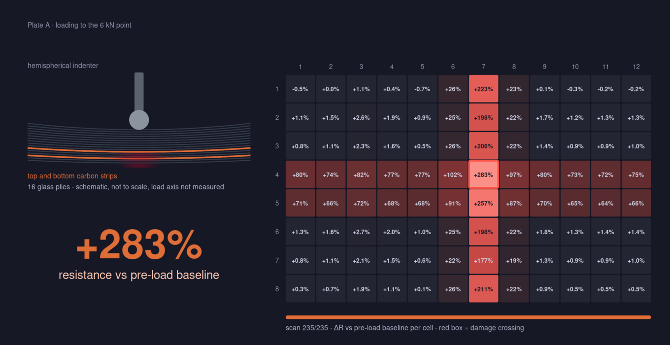
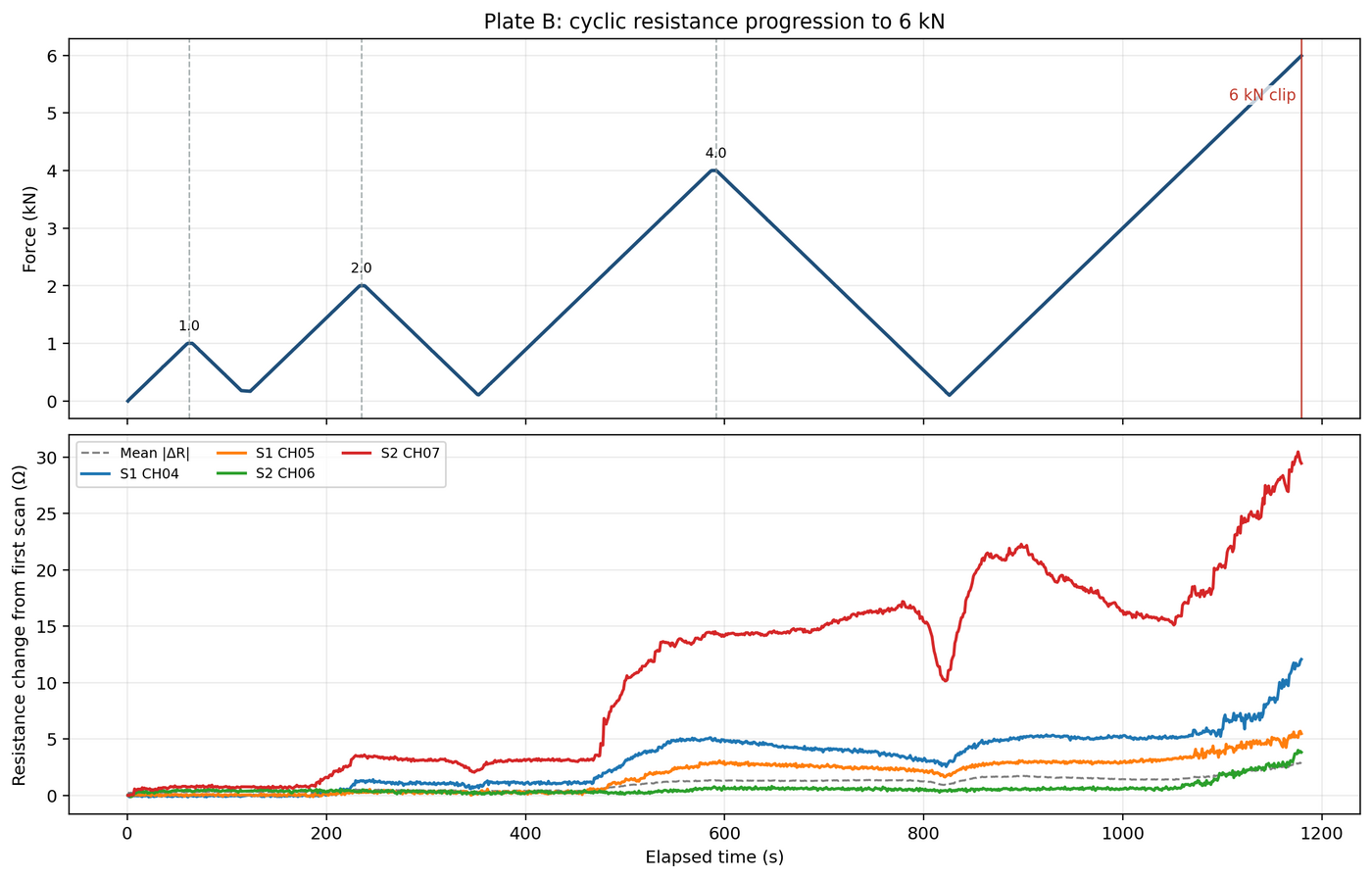
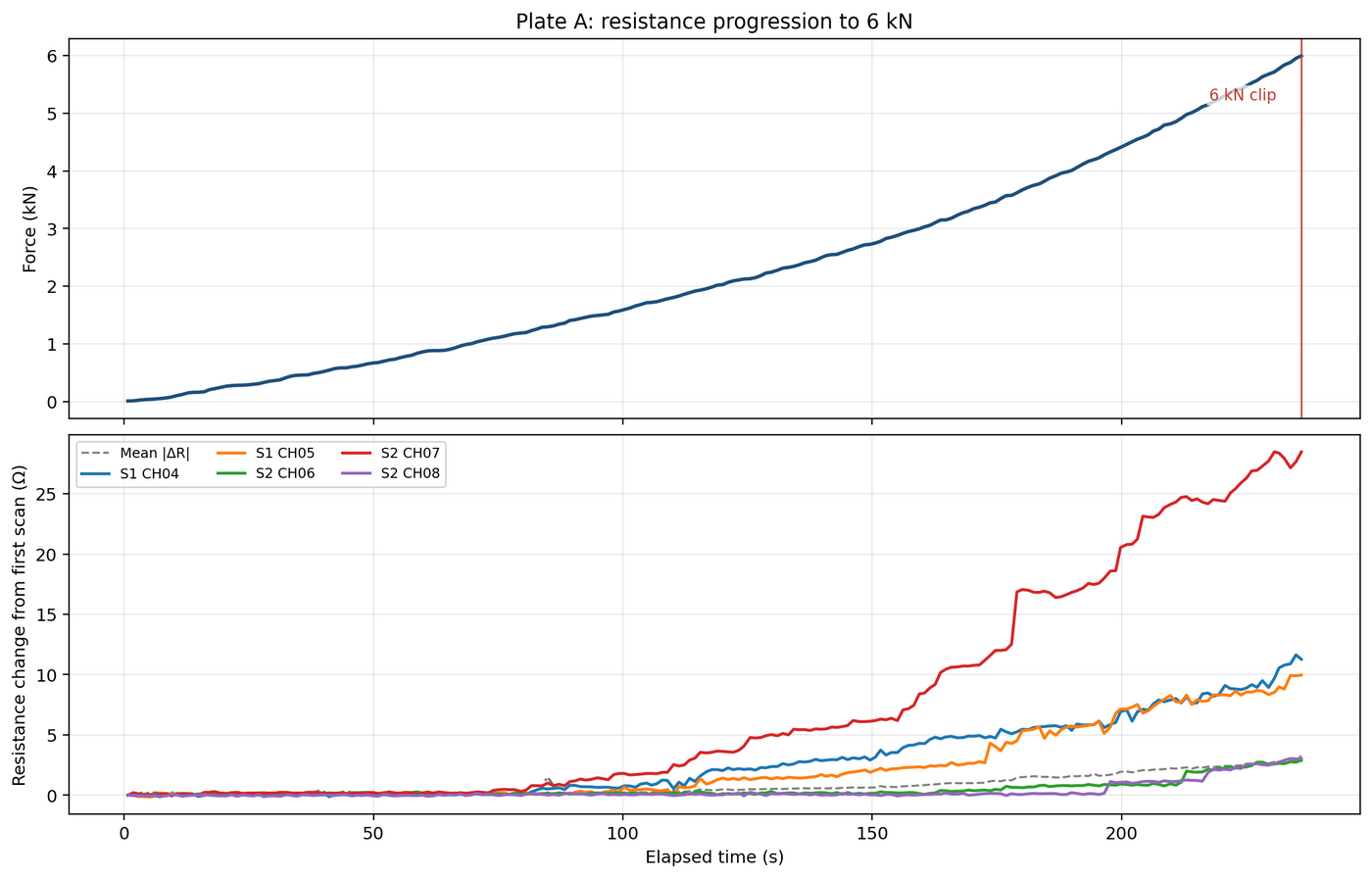
Broken fibers can't carry current, so resistance at the damaged crossing rises, and stays risen. At the 6 kN test point the hit channel climbs +41.6 Ω. The size of the resistance increase defines the damage and location.
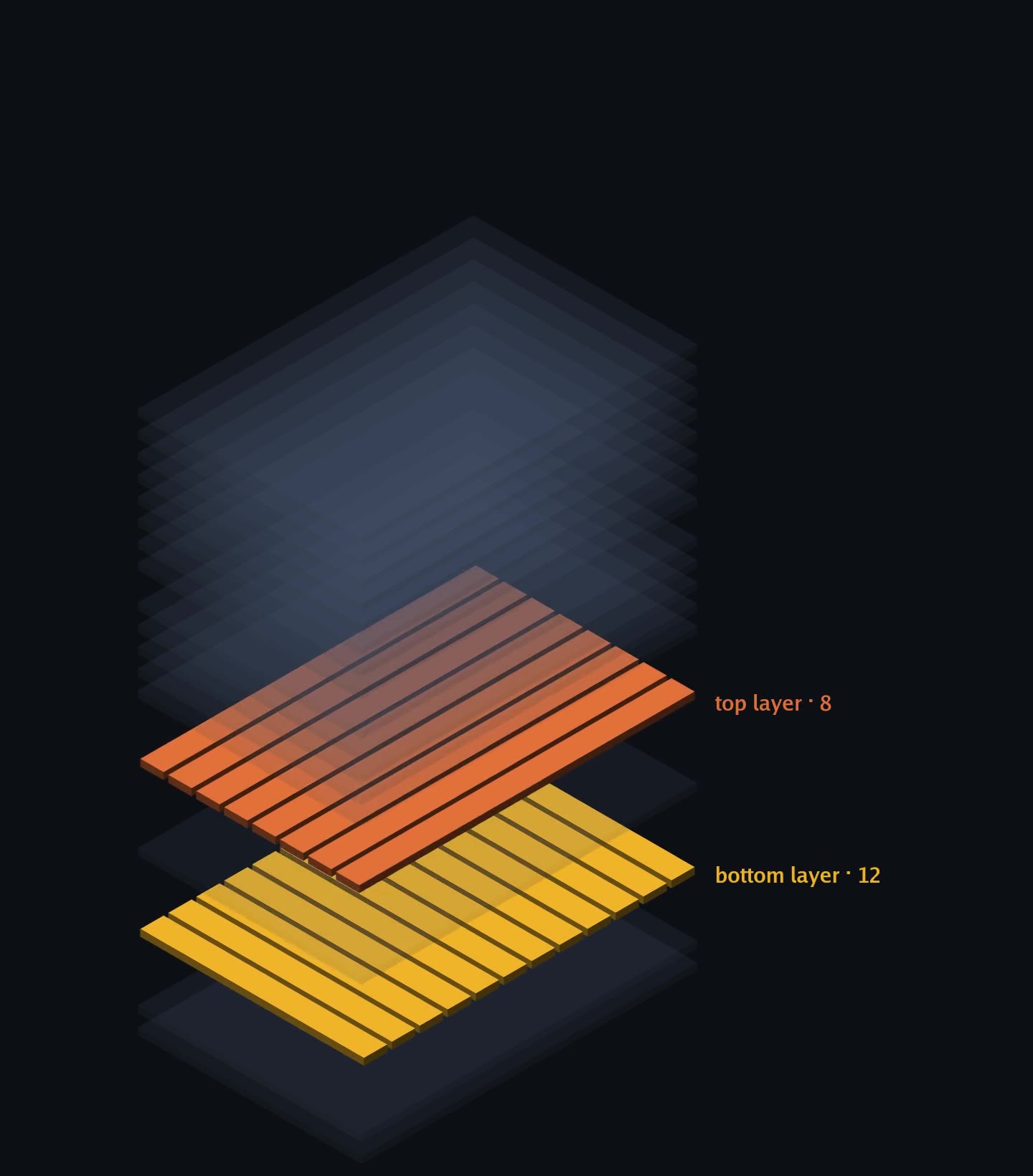
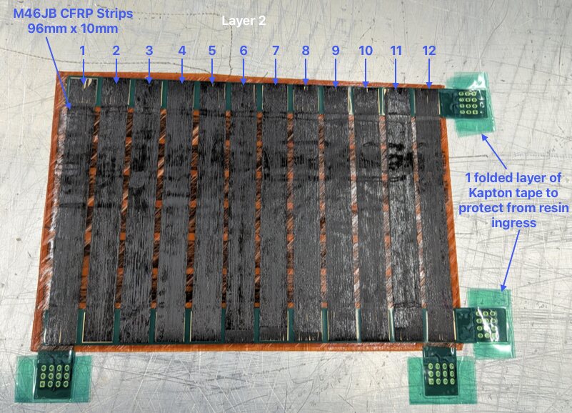
Two layers of carbon-fiber strips cross into an 8×12 grid, laid just below the midline of the laminate.
The grid is sealed inside the composite: no surface sensors, no bonded gauges, no added mass; fully integrated.
Every crossing is both a resistor and a capacitor. One grid, two physical signals, read independently.
Capacitance
pF · delamination
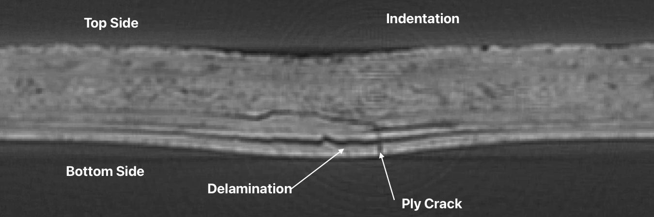
Compressed plies read high, delaminated plies read low, a severed strip reads zero: three damage signatures on one map, and the dead strips cross at the damaged area. This is the second sense, run as its own test with its own signature, so the map below reads a different condition from the resistance scan above.
Reading scale checked against known reference values: results land within +1.32% and +2.85%.
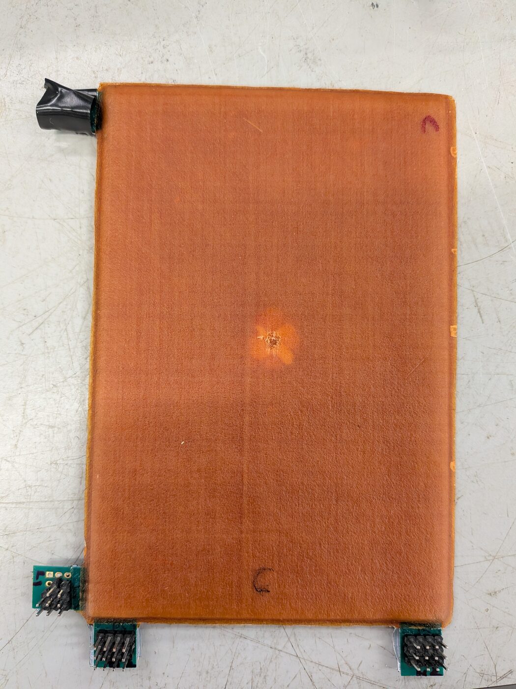
Loaded to barely visible indentation damage
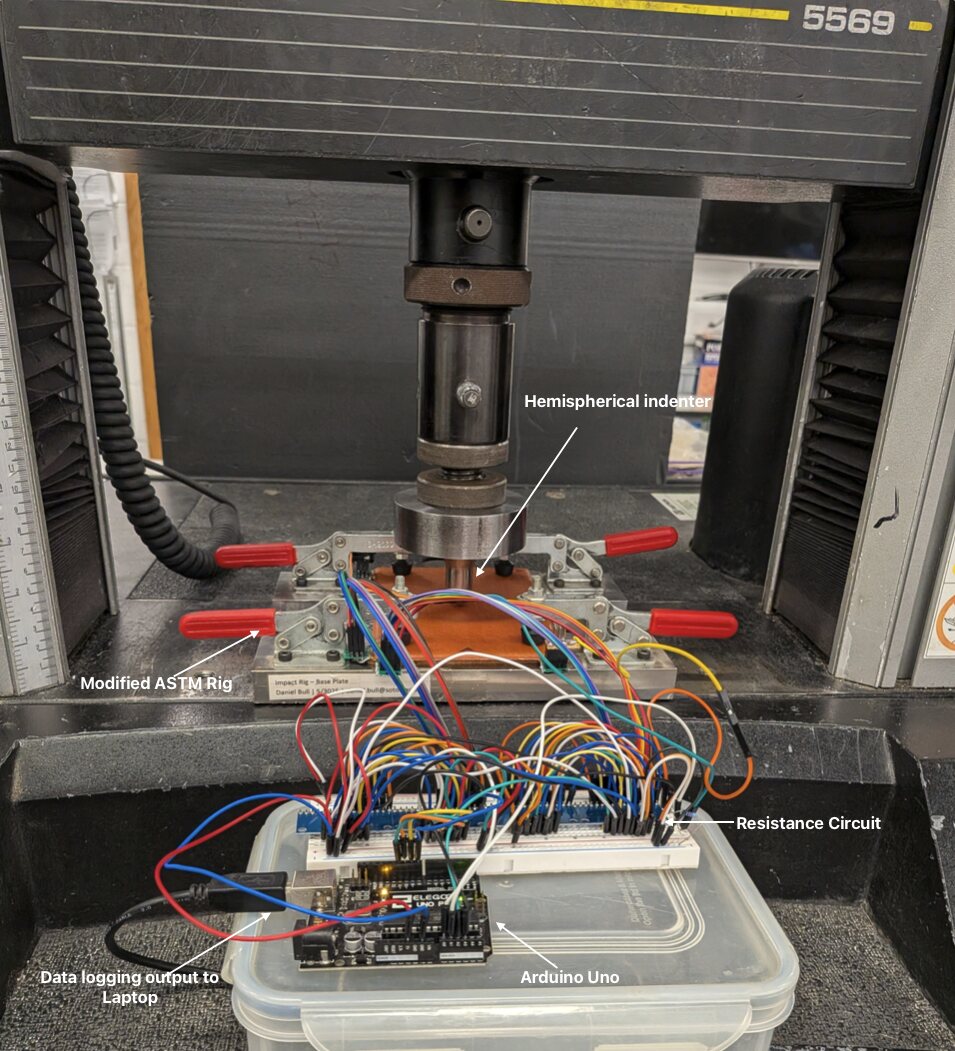
A hemispherical indenter pressed the plate slowly and steadily (quasi-static) to 6 kN while all 96 crossings were scanned continuously: 235 full-grid scans, live reading every cell.
The data
The material is the sensor
Structural health monitoring without external sensors: damage from resistance, delamination from capacitance, located to within 12 mm in one laminate.